In the vorticity plot, there is a bow shock like structure before the cylinder and then vorticity behind the cylinder. The explanation by @fb77 and results from the modified code present the same idea.
@fb77 Sir, can you please explain how the initial discontinuity on the left boundary is creating the vorticity wave.
Also sir, as artificial compressibility is a pseudo time. Does plotting the vorticity for smaller time means I should check the result after 5-10 iterations ?
This is a canonical flow and There are many results in the literature showing numerically irritational solutions using finite element methods in primitive variables. There are still problems with your method. At r a minumum: That is not the correct representation of the nonlinear term. You may be able to diagnose these problems more quickly/ easily if you formulare this as a newton iteration rather than a pseudo time stepping scheme. Note that there are no unsteady “vorticity waves” at steady state (though there could be a steady rotational component of the solution if the BC were rotational, which they are not).
I do not wish to go back and forth about this further. I wish you the best of luck and would encourage you to read up more on this subject.
If you look for an incompressible potential flow u=\nabla\psi with \Delta\psi=0, you can see that it cannot satisfy simultaneously that the initial velocity is zero \psi(t=0)=0 and the inlet boundary condition \partial\psi/\partial n=-1 on the left boundary for all t>0. Indeed if it were the case, take a smooth test function \varphi(x) which support touches arbitrarily the left boundary, but does not touch the other boundaries. Then \int_{\Omega}\nabla\psi\cdot\nabla\varphi=\int_{\partial\Omega_{in}}(-1)\varphi.
Since this holds for all such \varphi, and all t>0, this prevents to have \nabla\psi(t)\to 0 as t\to 0.
As a consequence the flow cannot be potential, therefore some vorticity is generated by the left boundary.
On the contrary if you do not put a discontinuity, for example by \partial\psi/\partial n=-t on the left boundary, then it becomes possible, thus in this case the flow remains irrotational.
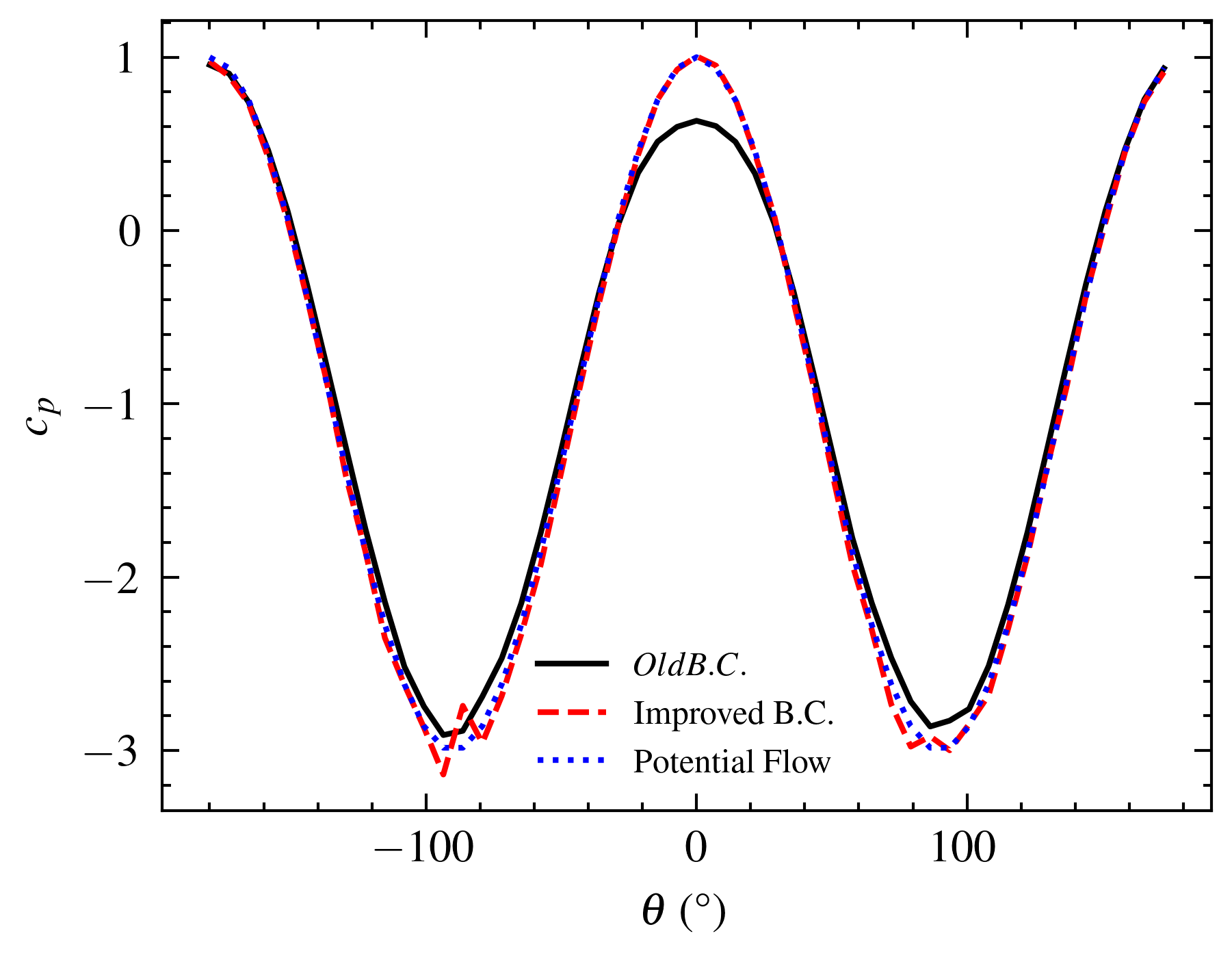
I discussed the problem with my guide. He suggested to use convective boundary condition on the outlet instead of not specifying anything. So, I implemented the following b.c \frac{\partial{u}}{\partial{t}} + u \frac{\partial{u}}{\partial{x}} = 0
And it worked like charm. I think the distortion at the top and bottom points on the surface of the cylinder can be corrected by increasing the number of points. I will check but overall this is a much better solution than the previous one.
I was mistaken previously when I said that there was some turbulence. This would be the case if we put no slip BC on the obstacle, which is not the case here.
About vorticity generation, I think that you could avoid it by setting no discontinuity on the inlet, as for example u1=t for 0<t<1, u1=1 for t>1, whatever are the BC on the outlet.
An additional remark: the inlet condition u2=0 (in addition to u1=1) is incompatible with the potential flow. Thus the steady state contains some vorticity. But the condition becomes compatible when the box becomes very large, thus in this limit you recover the potential flow.
Yes sir, it makes sense. As I move the inlet close to the cylinder body the flow is not normal to the inlet it is either curved upwards or downwards. Thank You sir for pointing the fact !
Indeed there is a simple argument to see that:
Assume by contradiction that there is a (transient or steady) potential flow u=\nabla\psi, satisfying u\cdot n=0 around the obstacle, and u=(1,0) at the inlet. Denoting u=(u_1,u_2), since u satisfies \mathop{\rm div}u=0 and \mathop{\rm curl}u=0, it follows that the couple (u_1,-u_2) satisfy the Cauchy-Riemann equations. Hence u_1-iu_2 is holomorphic in the domain. But on the inlet we have u_1-iu_2=1. By the principle of holomorphic continuation (using the Schwarz reflection principle to extend the domain of definition beyond the inlet) it follows that u_1-iu_2=1 in the whole domain, hence u_1\equiv 1 and u_2\equiv 0.
But this contradicts the condition u\cdot n=0 around the obstacle.
Next another remark is that if you put only the condition u\cdot n=-1 at the inlet (and no condition on u_2), you loose the uniqueness. Indeed you have a steady potentiel solution (that satisfies u_2\not=0 on the inlet), and at least another steady flow with non-zero vorticity (that satisfies u_2=0 on the inlet).